
Volume
6, Number 2, Spring 2006
REDUCING EARTH ELECTRODE
RESISTANCE BY REPLACING SOIL IN CRITICAL RESISTANCE AREA
Dr. P. Y. Okyere and*George Eduful
ABSTRACT
There are a number of methods which can be used to improve earth resistance of earth rods on sites where soil resistivity is high, replacement of the soil within its effective resistance area with more conductive soil being one of them. Replacing the soil in the entire effective resistance area is in general not practical. In this paper, the effectiveness of replacing soil in the critical resistance area only is shown by field tests. Application of this method requires calculation of earth rod resistance as a function of distance away from the rod. An analytical formula, derived and validated using test data to calculate these resistances, is also presented.
Keywords: Earth rod, earth resistance, soil resistivity, critical resistance area, grounding system
Introduction
The term grounding or earthing is defined as the connection of a conductor or frame of a device to the general mass of earth. Grounding is used for a number of good reasons. Primary among them is to ensure personnel safety. Others are to provide for the protection of plants and equipment; and to provide a safe path for dissipation of fault currents, lightning strikes, static discharges, EMI and RFI signals and interference.
In many of the applications of grounding, low earth resistance is essential to meet electrical safety standards. The resistance figure can vary from 10 ohms for lightning protection to below 0.1 ohm for many sites where protective devices must operate in a very short time due to the large fault currents involved [1]. The resistance figures also vary from industry to industry. Telecommunication industry has often used 5 ohms or less and certain Utility Companies use 10 ohms or less for high voltage distribution substations and 1 ohm or less for low voltage distribution substations [2, 3].
The earth resistance of electrode has three components: the resistance of the electrode conductor, the electrode/soil contact resistance, and the resistance of the soil surrounding the electrode. Typically, the first two components are negligible compared to the resistance of the soil. Thus most analytical formulae for earth electrode resistance usually account for the resistance of the soil only. The resistance may be considered as being made up of a number of concentric shells of earth or soil of equal thickness. If the soil is assumed to be of uniform resistivity, then the resistance of a shell varies inversely as its cross-section and therefore beyond some distance from the earth electrode, the resistance of successive shells will no longer noticeably affect the total earth resistance. Some study has shown that at a distance of about 1.1 times the length of rod electrode from the electrode, the resistance is about 95 % of the total earth resistance and change in resistance becomes negligible [4]. The area within this distance of the rod is the so-called effective resistance area. Measurements have also shown that about 90% of the total earth resistance surrounding an earth electrode is generally within a radius of 2 to 3 m from it [1].
The most versatile type of earth electrode is the driven rod. On sites where soil resistivity is high, the earth resistance is lowered using deep driven rods, rods with increased diameter, multiple rods, or using chemical compounds or soil of lower resistivity as an earth electrode backfill. Tests have shown that increasing the diameter of an earth rod from 12.5 to 25 mm has increased the weight by 400%, increased its cost by 400%, but only reduced the earth resistance by 9.5% [5]. Increasing the number of rods indefinitely also has little effect. The improvement in the earth resistance that can be expected from installing additional rod is: two rods 60%; three rods 45%; and four rods 35% [1]. If soil resistivity survey indicates lower resistivity at greater depths then a logical choice is the deep driven rods. However if soil resistivity is uniform then the percent reduction in earth resistance per unit length of rod becomes exponentially less with each increment of length [4]. The use of chemical compounds or soil of lower resistivity as an earth electrode backfill is a very effective method of dealing with high resistivity soil. Improvement in resistance values up to 20% has been recorded using chemical compounds as soil treatment agent [1].
A natural method of reducing earth resistance will be replacing all soil in the effective resistance area with soil of the lowest resistivity available. However this method may not in general make sense economically. For this to be realistic, it will be necessary to limit the backfill to the area very close to the earth rod and judged to be accounting for a substantial percentage of the total earth resistance. The area is referred to as critical resistance area and its radius as critical resistance radius. In this paper, the effectiveness of using a backfill in critical resistance area to lower earth resistance is demonstrated by field test data. One needs earth rod resistance as a function of distance away from the rod to apply this method of earth resistance reduction. An analytical formula for this is derived and validated with field test data.
Analytical Formula
for Calculation of Rod Electrode Resistance
A rod of radius r buried in the ground to a depth of l is shown in Fig. 1.
Assuming that the resistivity is constant, the earth resistance may be
derived from the general formula: ![]()
Consider an elemental concentric shell of
thickness ![]() and a distance
and a distance ![]() from the centre of the rod.
Then the resistance
from the centre of the rod.
Then the resistance ![]() of this shell is given by
of this shell is given by
![]()
Therefore the
resistance at ![]() is given by
is given by

This can be rewritten as
![]() (1)
(1)
As a large mass of the earth is taken into consideration the total earth resistance would be
 (2)
(2)
Fig. 1: Earth Rod in homogeneous soil
A plot of resistance R against distance x for the three rods used for the study is shown in Fig. 2. The rods are 0.5-, 1- and 1.4-m long and each has a diameter of 14 mm. The resistance is expressed as a percentage of the total earth resistance given by (2). The distance is also expressed as a percentage of the length of rod l. It is noted that the distance accounting for about 95% of the total earth resistance called effective resistance radius is around 350% but not 110% as reported in a previous study [4].
Fig.2 Variation of earth resistance with distance from earth rods
It is observed from Fig.2 that the resistance curves begin to saturate around 40% distance from the rods. Thus the 40% distance becomes a good proposition for the critical radius. This radius will be used as critical resistance radius for the study.
Methodology
Field tests were conducted to determine earth resistance as a function of distance from the three standard earth rods. An earth rod under test and twenty probes of length 0.3 m were driven into the ground in a straight line. The probes were spaced at equal intervals of 10 cm from the rod and used to measure resistances at their locations. Resistances were directly read in ohms with DET5/4R Digital Earth Tester. Its current probe was located at a distance of 30 m from the rod and in line with the twenty probes and the rod under test. The total resistance of the rod was measured applying the so-called “62%” rule [6].
The test was conducted at three different sites not far from each other and representative results reported. A photograph depicting the field testing is shown in Fig. 3.
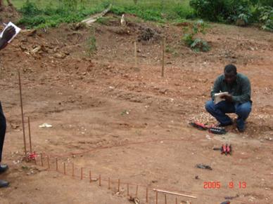
Fig.
3: Field Testing for Earth Rod Resistance as Function of Distance from the
Rod
To determine the effectiveness of the earth resistance reduction technique under study, the soil within the 0.4-m radius of the 1-m rod was removed and backfilled with soil of resistivity 5.7 ohm-m and its overall resistance measured.
Results and
Discussions
Representative results of the field tests are shown in Fig. 4. These are compared with results calculated with (1) in Figs 5, 6 and 7. Measured total resistances are also compared with analytically determined values in Table 1. From curves shown in Figs 5 and 6, one observes that the calculated earth resistances are in close agreement with the test results whereas there is discrepancy between the results for the 1.4-m rod shown in Fig. 7. The test and calculated results for the 0.5- and 1-m rods compare favourably because the top soil at the site where the field was conducted is close to homogenous (See photograph in Fig. 8). The difference in the measured value for the 1.4-m rod is due to variation of resistivity with depth.The measured resistances at critical radius of 40% are 71, 78 and 63% for the 0.5-, 1-, and 1.4-m rods respectively. The corresponding analytical values are 71, 75 and 76%, these again showing the homogeneous nature of the top soil at the site.
Fig. 4: Results of the field rod resistance test
Fig. 5 Comparison of calculated and measured resistances
of 0.5-m electrode in 15-ohm-m resistivity soil
Fig. 6 Comparison of calculated and measured resistances
of 1-m rod in 15-ohm-m resistivity soil
Fig. 7 Comparison of calculated and measured resistances
of 1.4-m rod in 15-ohm-m resistivity soil
|
Method |
Resistance in ohms |
||
|
0.5-m rod |
1-m rod |
1.4-m rod |
|
|
Analytical Formula (2) |
20.5 |
11.9 |
9.0 |
|
Field test results |
20.7 |
13.0 |
12.6 |
|
Table 1. Comparison of measured and calculated resistances (ρ =15 ohm-m) |
|||
The 1-m rod in a soil of resistivity 15 ohm-m gave a total earth resistance of 13 ohms. When the critical resistance area was backfilled with soil of resistivity 5.7 ohm-m, the resistance dropped to 4.7 ohms representing an improvement of over 65%. It can be shown that when soil within a given radius of earth rod is replaced the formula derived above takes the following form (See appendix):
![]()
Where
![]() and
and ![]() are resistivities of
the local soil and the backfill respectively and
are resistivities of
the local soil and the backfill respectively and ![]() is the resistance at
the given radius as a fraction of the total earth resistance in a homogenous
soil. For the 1-m rod, this is given by
is the resistance at
the given radius as a fraction of the total earth resistance in a homogenous
soil. For the 1-m rod, this is given by
![]()
The improved resistance, by the above formula, is found to be 6 ohms. This value again is consistent with the measured value of 4.7 ohms. The formula shows that degree of improvement depends on the ratio of local soil resistivity and the backfill resistivity.
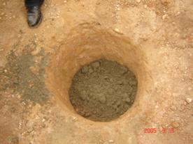
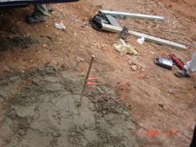
Fig. 8: Backfilling a critical cylinder with lower resistivity soil
Fig. 7 shows a photograph of a critical cylinder being backfilled with lower resistivity soil.
Conclusion
Field test data has been presented to show the effectiveness of backfilling the critical resistance area of earth rods with more conductive soil. Analytical formula to calculate earth resistance of earth rods in terms of radial distance from rod has been derived and validated with field data. Resistances calculated with this formula are found to be consistent with the field test data.
Reference:
[1] E.A. Reeves, Handbook of Electrical Installation Practice, BlackWell Scientific Publications, 1990 pp 181 – 194
[2] J.B Gupta, A course in Electrical power, S. K. Kataria & Sons Publishers October, 2001 pp
[3] S.L. Bhatia, Handbook of Electrical Engineering, Sixth edition, Khanna Publishers pp 505
[4] Roy B. Carpenter Jnr., Joseph A. Lanzoni, Designing for a Low Resistance Earth Interface (Grounding), A LEC Publication. Revised July, 1997.
[5] Consultants Handbook ‘Recommendations for the Protection of Structures against Lightning’ W. J. Furse & Co, Ltd, wilford Road Nothingham
[6] Getting Down to Earth (A manual on earth resistance testing for the practical man), April, 1981. pp 16-17.
Appendix
If soil resistivity within the critical
radius ![]() is
is ![]() and soil resistivity external to the critical radius is
and soil resistivity external to the critical radius is ![]() , then
, then
 =
=


![]()
Where  =resistance as a fraction of the total resistance if soil is
homogenous.
=resistance as a fraction of the total resistance if soil is
homogenous.