
Volume 2, Number 1, Fall 2001 (Software Review)
Mechanism Design in I-DEAS
Daniel M. Chen
Central Michigan University
Email: chen@iet.cmich.edu
ABSTRACT
Many integrated CAD software of today are capable of performing mechanism design based on solid model data.� With I-DEAS, users can use the pop-up windows to enter their input data in the mechanism design application.� After each run, they can go back to any window, change one or more design parameters and execute another run.� In addition, the graphs for geometric properties, which include displacement, velocity, and acceleration, can be viewed once the mechanism is solved.� Users can revise the design quickly using these geometric properties without dealing with underlying mathematical tools.� They save tremendous amount of time by eliminating laborious manual construction required for the traditional approach.
MECHANISM DESIGN AND ITS APPLICATION IN CAD
A mechanism is a combination of two or more machine parts such as: linkages, couplers, gears, and cams, function together to perform a specific motion.� A machine will usually consist of one or more mechanisms to transmit and convert energy into work.1� The design and analysis of a mechanism traditionally involve manual construction of the graphs for geometric properties that include displacement, velocity, and acceleration.� Vector polygons are usually used to determine velocity and acceleration one position at a time.� This laborious process must be repeated for a number of positions until the entire cycle is completed.� Although the graphical differentiation as an alternative is also available, the displacement curve needs to be drawn first before it is graphically differentiated for the velocity curve.2� This time-consuming, yet less-accurate process must be repeated for the acceleration curve.
The parametric software, such as I-DEAS, has various engineering applications that can be used to predict the outcome of designs early in the product development cycle.� One of these powerful applications is mechanism design that enables users to put the solid parts of a machine into motion without actually building one.� And under these simulation conditions, parameters such as limits of motion, interference, and geometric properties can be determined.� Mechanism design in CAD is crucial to the world of design, because few products designed today do not have moving parts.� The purpose of this article is to address the functions and capabilities of mechanism design in I-DEAS.
OPERATION OF MECHANISM DESIGN IN I-DEAS
The process of mechanism design in I-DEAS begins with the creation of solid parts.� It is followed by the creation of assembly hierarchy.3,4� In order to demonstrate how the operation of mechanism design is completed in I-DEAS, a simplified engine assembly as illustrated in Figure 1 is used as an example.
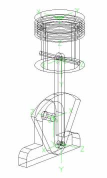
Figure 1. Engine Assembly
The assembly hierarchy is displayed in a form that lets the user build the assembly according to the relationship of one solid part to the other.� In this case, the title is �Engine Assembly� which serves as the parent for the hierarchy tree.� As shown below, the user can add to this tree with the supporting block, crankshaft, connecting rod, and piston sub-assembly that includes piston and pin:
��������������������������������������������� �� Engine Assembly
����������������������������������������������������������� Supporting Block
����������������������������������������������������������� Crankshaft
����������������������������������������������������������� Connecting Rod
����������������������������������������������������������� Piston Sub-assembly
����������������������������������������������������������������������������������� Piston
����������������������������������������������������������������������������������� Pin
Before the mechanism can be solved, the user needs to apply proper joints to the system, apply proper grounds to non-moving parts, and define motion input to one or more joints.
The ground, in this case, is the supporting block.� All joints are revolute joints except the one between the piston and supporting block that requires a translational joint.� The locations of these joints (in green) are also shown in Figure 1.� As to the motion input that needs to be assigned to the revolute joint between the crankshaft and supporting block, the user is given the choice of either constant or time dependent.� The result produced from the internal solver of I-DEAS predicts the motion output of all parts.� Before the internal solver is activated, the user must define the end time (in seconds) and number of steps in that same period of time.
WHAT MECHANISM DESIGN IN I-DEAS DELIVERS
The typical outputs of mechanism design include (1) animation and (2) graphical result of geometric properties.� The user usually animates the motion first after the mechanism is solved.� The capability of 3D animation would allow configurations be automatically stored for the specific steps of motion.� To complete an animation sequence for the engine assembly, the crankshaft rotates 360 degrees as the piston moves up and down until the number of steps have been completed.� The animation gives the user a better sense of the motion of each part relative to others in a mechanism.� The user can also easily check limit of motion and interference, which is extremely difficult with the traditional 2D drafting approach.� The graphs of the linear and angular displacement, velocity, and acceleration of any part of interested can be plotted as a variable of time.�� The user can use this information to modify existing design by targeting the right area for improvement.� Figure 2 shows the displacement of the piston, one of such graphs as an example.� It is generated with a motion input of 1 revolution per second (60 rpm) for the crankshaft and 12 steps in one second of end time.
 |
Figure 2. Displacement of Piston as A Dependent of Time
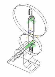
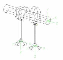
Mechanism design can be carried out for various types of joints and constraints.� It can be used for not only revolute and translational joints, but also cylindrical, spherical, universal, planar, and fixed joints.� They can also be used for couplers, gears, point/cam or cam/cam constrains.� Figure 3 shows a planetary gear train that consists of a sun gear, a planetary gear and an arm.� The planetary gear rotates about its own axes and also around the sun gear.� When applying joints to this system, all joints are revolute joints except the one between the sun gear and planetary gear � it requires a gear constrain (in blue).� A gear constrain would allows the calculation of the gear ratio based on their pitch diameters to take place.� Figure 4 illustrates a cam-follower assembly that consists of a camshaft with two disk cams, and two valves.� There is a cam/cam constraint required between each cam and valve stamp.� Other constraints include a revolute joint between the camshaft and the cylinder head (not shown) and a translational joint between the valve and the cylinder head.
Figure 3. Planetary Gear Train Figure 4. Cam-Follower Assembly |
I-DEAS AND ITS INSTALLATION
I-DEAS stands for Integrated Design Engineering Analysis Software.� Major corporations, such as Ford Motor Company and Xerox Corporation, have adopted the software for worldwide product development.� I-DEAS has a wide range of applications.� They include drafting, design, simulation, test, and manufacturing.� Each application consists of a number of tasks.� In design application, there are tasks in Master Modeler, Master Assembly, Mechanism Design, Tolerance Analysis, and Sheet Metal.� The creation of solid parts is completed in Master Modeler before their instances are used to set up assemblies in Master Assembly.� The creation of joints/constraints, grounds, input motions, and solution that includes animation and geometric properties are all achieved in the task of Mechanism Design.
I-DEAS has a very powerful application in simulation.� The primarily tasks in simulation are for finite element modeling.� Other tasks include Response Analysis, Laminates, Moldflow, Thermal Analysis, Electro-System Cooling, and Vibro Acoustics.� The most current version, I-DEAS 8, runs on either the Unix systems or PCs with Window NT.� The recent student edition of I-DEAS can be run on a PC with Window 4.0 or Window 2000.� It has a simplified installation procedure.� The features provided in student edition include high productivity 2D drafting; 3D part design, assembly, surface modeling, and rapid prototyping drivers; toolpaths for milling and turning.
CONCLUSION
With the proper backgrounds in kinematics or mechanism/mechanical design, most users should be able to adapt to different functions in the software quickly.� As they becomes experienced with the software, they would build and analyze a machine much more efficient.� Since it is so easy to have the access to geometric properties, users can afford to make as many design revisions as necessary without dealing with mathematical details.� With the application of mechanism design in CAD, users have acquired not only a powerful tool that greatly enhances their design skills, but also deep understanding of the concepts and principles in mechanism design along the way.
REFERENCE
- Machines and Mechanisms, David H. Myszka, Prentice Hall Inc., 1999. ISBN 0-13-597915-3
- Kinematics-A Graphical Approach, Jerome C. Lange, Prentice Hall Inc., 1995. ISBN 0-13-125303-4
- The I-DEAS Student Guide, Mark H. Lawry, Structural Dynamics Research Corporation, 1999. ISBN 0-9638178-2-5
- The Fundamentals of I-DEAS Course Guide, Structural Dynamics Research Corporation, 1996.
BIOGRAGHICAL INFORMATION
Dr. Daniel M. Chen is currently the professor and chairperson of the Department of Industrial and Engineering Technology at Central Michigan University.� He completed his undergraduate studies in mechanical engineering at Taipei Institute of Technology, Taipei, Taiwan.� He also holds an M.S. from South Dakota School of Mines and Technology and a Ph.D. from Kansas State University in that same discipline.� He is a licensed engineer in the State of Michigan and a member of the American Society of Mechanical Engineers, Society of Manufacturing Engineers, and American Society for Engineering Education.� Dr. Chen has taught various courses in mechanical engineering technology including kinematics, dynamics, mechanics of materials, machine element design, fluid mechanics, thermodynamics, etc.� His current research interest is in computer-aided design (CAD) and computer-aided engineering (CAE).� He is offering a number of courses in both solid-based modeling and engineering analysis.
Last Updated On 8/29/2005