
An Interdisciplinary Approach: Rapid Prototyping at Penn State Altoona
|
Rebecca A. Strzelec Division of Arts and Humanities Pennsylvania State University Altoona College ras39@psu.edu |
Andrew N. Vavreck Division of Business and Engineering Pennsylvania State University Altoona College axv2@psu.edu |
ABSTRACT
Fused deposition modeling (FDM) is one of many prototyping techniques available for building three-dimensional tangible models of mechanical parts for use during the design process. In the senior capstone course for electromechanical engineering technology (EMET) students at Penn State Altoona, a FDM system is used to create part concepts and test them for fit and function. But the FDM has much broader applications throughout the program and across the campus, as the centerpiece of a unique partnership between art and engineering faculty. “CAD for Artists”, an introductory level art course that includes the use of the FDM machine, is taught concurrently with the capstone design course. In addition to the use of rapid prototyping technology among undergraduate students, and for faculty research, outreach occurs each spring in the form of the W.I.S.E. program for several dozen middle school (11-13 year old) female students from south-central Pennsylvania.
INTRODUCTION
Penn State Altoona, one of 24 Penn State campus locations in the Commonwealth of Pennsylvania, is located in the south-center of the state, about an hour’s drive southwest of the main campus in State College. The campus is undergraduate and residential, with an enrollment of around 4,000 students. Penn State Altoona is a College of the University, and offers three engineering technology degrees: associate degrees in mechanical and electrical engineering technology (ME T and EE T) and a baccalaureate degree in electromechanical engineering technology (EMET). The EMET degree, a 2+2 program, graduates about 30 students a year, most of whom have graduated from one of the associate technology courses at the campus. The campus is one of four campuses of Penn State to offer a BS in EMET, and at Altoona, the program emphasizes manufacturing and automation.[1] The students gain skills in a wide variety of technologies and have available state-of-the-art laboratories, including CAD, controls, and automation. A machine shop and projects area are also available. The projects area is used for annual student design competitions, including SAE Mini Baja and the ASME Student Design Contest and for student projects as part of the EMET capstone design course.
One of the most useful tools students have to help with the development of their capstone design projects or student design competitions is the fused deposition modeling (FDM) system. The FDM allows students to quickly build three-dimensional ABS (Acrylonitrile-Butadiene-Styrene) models of design concepts, to try out fit and functionality, but the most common use is as actual components of the system being developed. As a structural material, the ABS plastic is limited, but for prototype devices, many of which are small-scale, appropriate applications can be found and the FDM system’s speed and accuracy can be exploited. The FDM is used in concert with a software application, Rhinoceros,[2] which makes incorporating aesthetic elements of design more feasible.
FDM has been used in many student projects in engineering and engineering technology programs at other universities for a variety of purposes. Many curricula make use of rapid prototyping equipment in regular courses. Examples include use of rapid prototyping equipment in manufacturing,[3] manufacturing technology,[4] architectural,[5] mechanical engineering technology,[6] and mechanical engineering[7] curricula. Outreach is also enhanced at some campuses by the availability of a rapid prototyping system, involving middle[8] or high school[9],[10] students.
The FDM system at Penn State Altoona was brought to the campus in 2003 to enable the research of a new faculty member in visual arts (this paper’s co-author) and since its introduction it has opened up many opportunities for including this technology in engineering technology classes, including CAD and machine element design. It has also led to collaborative opportunities between Art and Engineering, including involvement by EMET students in an orientation and design course with the FDM, consultation on design aesthetics, and FDM operation with art faculty members and a joint art-engineering outreach effort to middle school girls. The collaborative environment made possible by the FDM machine and supporting software have greatly enhanced the engineering and art programs at the campus, and have created many opportunities for future growth.
The paper describes
DESCRIPTION OF THE FDM
Created in 1989 by Scott Crump, Fused Deposition Modeling, or FDM, was one of the first commercially viable rapid prototyping technologies. Now a part of Stratasys Inc.,[11] FDM has become an ideal solution for a diverse range of prototyping needs.
Today there is an array of materials available for extrusion in the various FDM machines they include: ABS (Acrylonitrile-Butadiene-Styrene) plastic, polycarbonate, polyphenylsulfone, and proprietary UV plastic. Depending on the machine used objects can be as large as 59.9 x 50.0 x 59.9 cm. Default coloration for the material is white or clear. ABS can be ordered in any custom pantone color or in any of the 5 basic colors including black, red, blue, green, and yellow. In addition to the model material the FDM process also uses a temporary break away or water soluble support material laid down to attach the model to the build platform and bolster interior parts, negative space, holes, overhangs, and undercuts. The cost of material varies slightly depending on the quantity purchased and the vendor but averages USD 250 per cartridge for both model and support. With 878 cubic centimeters in a new cartridge the cost of material to build models is approximately USD 0.27 per cubic centimeter.
The FDM process begins with a three-dimensional model. This model must be completed, without geometry issues such as flipped “normals” or “naked edges”, within a solid or NURBS modeling environment such as Auto CAD, PRO E, or Rhinoceros (Figure 1). The native three-dimensional model file format is then exported as a Stereolithography or STL file format extension. The STL file is then opened in Catalyst (Figure 2), the software package supplied with the FDM Dimension modeler, so it can be prepared for prototyping. Once in Catalyst the model can be oriented either by surface selection or degree input to minimize supports, thus minimizing cost and time of build. Depending on the degree of detail and function of the model build style can be changed from draft to standard resulting in slice layers that are .33 and .245 mm respectively. The model’s interior style can be built “solid” with no hollow interior space or “sparse” where minimal scaffolding like threads are build within internal spaces resulting in a semi-hollow part, again affecting cost and build time. After selecting the build and support style for the model an analysis procedure begins resulting in the establishment of a CMB file. The CMB file consists of multiple standard files generated by creating slices, supports, boundary curves, and tool paths for the model.
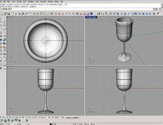
Figure 1: Three-dimensional model of a wine glass as seen in Rhinoceros
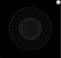
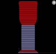
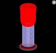
Figure 2: Wine glass as seen in Catalyst as cross-section, from front, and in perspective view. Support material is shown in purple while model material is shown in red.
Slices are created horizontal to the x axis dividing the STL file into a stack of two-dimensional part boundary contours. Once the slices are compiled the support material is generated automatically. The design and location of the support material is dictated by the geometry of the model. After slicing and support generation boundary curves, or closed curves used to define a region in the xy plane, are completed. Two different types of boundary curves are found in the analysis of a model: part boundary curves, which are a result of slicing, and support boundary curves which are a result of support generation. Finally tool paths, the data used to describe extrusion tip positioning is produced. The model is then shown in its sliced state with color coded representation of its supports and boundary curves. Models can be examined further, if need be, by stepping through each consecutive slice layer to determine if model and support material exist in the proper places. The model is then placed on a graphic representation of the build table and can be saved or sent to the machine for prototyping. If saved, the model can later be merged with other pending jobs to maximize platform use. If sent to the machine, via a network connection, an approximate build time is supplied. The status of the machine, material, and build time remaining can be monitored via a designated IP address as well as directly on the machine interface.
In the building process (Figures 3 and 4), the FDM machine feeds a continuous thread of material through a heated nozzle, approximately 138°C, where it melts almost to the point of liquefaction. The heated thread extrudes according to the tool paths created in the CMB file. Once the material is extruded from the nozzle it immediately hardens in its temperature-controlled environment and adheres to the layer beneath it. This additive process occurs for each slice layer until the entire part has been deposited. Part build time varies according to geometry size but falls roughly at 5.5 minutes per cubic centimeter.
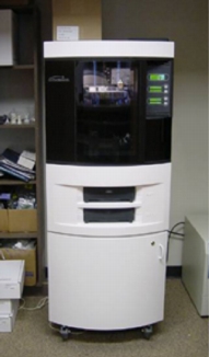
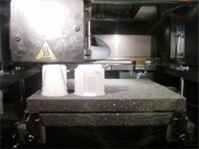
Figures 3 and 4: Penn State Altoona’s Dimension FDM machine and view of build in progress
Once the building cycle is complete the part can be removed from the machine immediately. The part is released from the build platform and all supports are either broken away or dissolved in an ultrasonic tank depending on the type of support material used. There is no further post-processing needed. Many of the model materials in FDM are suitable for sanding, priming, painting, and machining.
MECHANICAL PROPERTIES OF FDM ABS
The properties of FDM-deposited ABS differ from those of cast ABS because of the deposition process.[12] The FDM process lays down beads (or roads) or semi-molten plastic, so the material is, unlike cast ABS, anisotropic. The bead orientation (raster direction), bead width and the amount of spacing between adjacent beads (air gap) all affect the mechanical properties. The materials testing reported in Ahn was performed on FDM (Stratasys 1998 model) P400 ABS specimens with various raster orientations and two air gaps. Injection-molded ABS specimens had a tensile strength of about 26 MPa, while FDM ABS specimens with roads oriented in the direction of tensile stress had a tensile stress of about 20 MPa. If the load is applied with the beads alternating in layers at +45° and -45°, the tensile strength was reduced to about 12 MPa. The lowest tensile strength occurred for beads oriented at 90° to the loading (the build plane perpendicular to the load direction). Tensile strength under this condition was about 3 MPa. Air gap affected tensile strength as well, with specimens constructed with a negative air gap (adjacent beads slightly overlapping) being stronger than specimens with the beads just touching (zero air gap). Compressive strength was found to be about 40 MPa for injection-molded ABS P400, about the same when the build layer plane was oriented in the load direction, and about 35 MPa when the build layer plane was perpendicular to the load. Bead width, color and model temperature had negligible effect on the tensile strength. Another paper[13] reported tensile testing results for ABS deposited by a Stratasys 1650 RP machine. This paper indicated the highest ultimate and yield strengths (at 0° orientation) at 20.5 and 16.3 MPa respectively, and ultimate and yield strengths at ±45° orientation at 13.7 and 10.3 MPa. The weakest orientation was in this case the 45° orientation (no alternating bead angle in adjacent layers), with ultimate and yield strengths of only 7.0 and 6.6 MPa. For comparison, 6061-O wrought aluminum alloy has a tensile strength of 124 MPa.[14]
The authors in Ahn also gave very useful guidelines for use of FDM ABS plastic in structural elements:
· Small bead width increases build time, but improves surface quality.
· Wall thickness should be an integer multiple of bead width to avoid air gaps.
· Two-dimensional slices closely reproduce geometry.
· Three-dimensional layer stacking creates linear approximations.
The manufacturer of the machine used at Penn State Altoona, Stratasys, lists the material properties in Table 1 (converted from USCS units; no indication was made of the bead orientation in which specimens were tested).[15]
Other material properties of ABS (injection molded, medium-impact grade) include specific gravity of 1.03-1.06 g/cc, hardness of Rockwell R102-115 (a fairly high hardness for a thermoplastic polymer), and a deflection temperature under flexural load of 455 kPa of 93.3-104.4°C (a fairly low heat deflection temperature).[16] FDM ABS is thus suitable as a structural element for low load, low-temperature applications, especially where weight savings and the ability to quickly fabricate complex, dimensionally-accurate parts are desirable qualities.
Table 1: Material Properties (Stratasys)
|
Material Type |
Liquefier Temp (°C) |
Build Speed (cm/sec) |
Notched Izod Impact Strength Average (J/m) |
Peak Flexural Stress (MPa) |
Flexural Module Average (GPa) |
Peak Tensile Stress Average (MPa) |
Tensile Modulus Average (GPa) |
Break Elongation Average (%) |
|
ABS FDM |
290 |
5.08 |
114.8 |
34.3 |
1.21 |
21.6 |
1.64 |
3.18 |
|
Polycarbonate FDM |
340 |
5.08 |
100.4 |
76.3 |
1.46 |
52.6 |
1.96 |
3.6 |
|
ABS Injection Molded |
- |
- |
133.4 |
62.1 |
2.21 |
30.3 |
1.86 |
50-95 |
|
Polycarbonate Injection Molded |
- |
- |
640.5 |
93.1 |
2.31 |
65.5 |
2.48 |
120 |
EXAMPLE CAPSTONE DESIGN PROJECT APPLICATIONS
The capstone Electromechanical Engineering Technology design course, EMET 440, requires students to design and construct a device that draws on both their electrical and mechanical backgrounds, and involves some form of computer control. The course is offered in the last semester, and typically involves teams of two, who develop a project proposal, plan and track the project using project management software, make several oral presentations on their progress, and submit regular status reports and interim and final reports.[17] The final week of the class includes oral presentations on the projects before an audience of faculty, students, advisory board members, family members and other guests from the community. The FDM has become a major element in the design and fabrication phases of the projects. Serving to illustrate how the FDM was used in capstone design projects are a load-lifting waterwheel system and radio-controlled, infrared-targeting paintball tanks. The projects were performed during the 2002-2003 and 2003-2004 academic years, respectively. Students on both project teams enrolled in the Spring Art 100 course concurrently with their capstone design course.
In a project to compete in the 2003 ASME Student Design Contest, and as part of their EMET capstone design project, a team of two designed and built a water wheel. The wheel was designed to have the water buckets arranged on a belt, suspended vertically between two pulleys. The water wheel lifted a cart filled with uncooked rice, simulating a water-powered mine ore lifting system. The water buckets had to be light and uniform, and shaped carefully to enable smooth flow and balance, including holes for attachment to the belt and an overflow notch. The FDM was used to fabricate buckets for the wheel (Figure 5, including a US half-dollar coin, diameter 30.6 mm, for scale), and to make the “ore” cart, which had to be lightweight and dimensionally accurate as well.
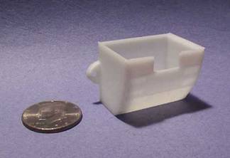
Figure 5: Water Wheel Bucket
Two teams in 2003-2004 designed and built paintball-shooting tanks as part of their capstone design course. The tank chassis were remote controlled (radio frequency). A turret on each tank, carrying infrared emitters and detectors and the paintball gun, automatically aimed and fired on the opponent tank as the teams remotely maneuvered the chassis. Both teams agreed on the emitter specifications, and the rules of the actual competition. Both teams used the FDM to fabricate a housing (Figure 6, including a U.S. half-dollar coin for scale) for the infrared detectors. An array of five IR detectors are arranged in an arc, and the signal strength from the detector array is used to automatically control the turret azimuth and signal for the gun firing (when the side-shielded center detector is on) as the tank chassis is maneuvered. The application made good use of the FDM’s ability to quickly produce a lightweight structure in a complex shape, where load requirements were low. The second team used the FDM to fabricate a brush holder for a slip ring to connect the turret electronics to the chassis.

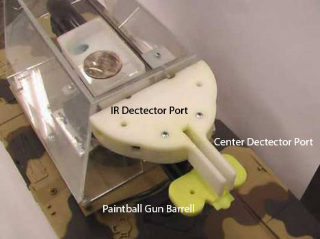
Figure 6: Paintball IR Tank
EXPERIENCES IN ART
Today various disciplines are employing RP technologies more readily as the cost running the machine have decreased dramatically. Artists have taken notice to this new availability and are incorporating RP into their work. Many artists using RP have access to a machine either through industrial relationships, university research, or by outsourcing to service bureaus.
One of these artists, Rebecca Strzelec, Assistant Professor of Visual Arts and co-author of this research, began teaching at Penn State Altoona in 2002. Early that semester the College purchased a FDM machine to support Strzelec’s creative activity and for use in curriculum. Having graduated from Tyler School of Art in Philadelphia, Strzelec studied with Stanley Lechtzin, a pioneer who first brought CAD and RP in to the academic Craft discipline. Strzelec completed all of her graduate thesis work via CAD and RP. While her work has evolved conceptually it still remains in a technological vein through the combination of engineering, and craft. The Shorthand Series, Strzelec’s recently completed body of work, creates a dialogue about the technology she employs through the juxtaposition of forms inspired by the defunct stenography language Gregg Shorthand. This series consists of 12 pieces inspired by the shorthand words: Apology, Autopsy, Alone, Altoona, Drip, Fib, Line, Manipulate, Prepared, Solid, Typical, and Unpoetic (Figure 7).
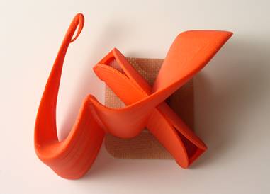
Figure 7: Strzelec’s Apology Brooch, from the Shorthand Series, c.2004
Strzelec’s dedication to this kind of art making has led to the addition of ART 100, Beginning CAD for Artists, at Penn State Altoona. In this course students are challenged to think of the computer as an artistic medium, similar to drawing, painting, or sculpting and therefore are expected to create concept-driven pieces with aesthetic value. The first part of the semester is spent learning the interface of the three-dimensional NURBS modeling application Rhinoceros. Students are led through a series of tutorials that introduce all of the different functions within the program. Many of the tutorials result in the making of a simple everyday object like a screwdriver, bottle, or wine glass. Beginning at the sixth week of the semester students are asked to complete their first of three original objects, a set of salt and pepper shakers that are inspired by a contemporary sculptor.
The shakers end up more like mini-sculpture than highly functional table ware, which is not to say that they don’t work. They do. But because the class is an art making experience the students are urged to venture beyond conservative scale and symmetry. Using all of the tools they mastered during the tutorial stage of the course the students are able to create build-able, referred to as “water-tight” by the industry, models that can translate to the RP machine with no geometry issues. Beyond the CAD file which contains the object and the tangible FDM part students are also asked to create a photo-realistic rendering of their piece. This allows the students to assign attributes like color and surface finish to their pieces as well as stage and light their two-dimensional compositions.
Other assignments include the re-design of a chess piece for inclusion in a class collaborative chess set, and a final assignment which allows for the students to choose between creating a writing utensil, a piece of jewelry, or a set of cookie cutters celebrating an unusual holiday or event. Tangible rapid prototyped parts are displayed in prominent cases outside of the college’s two art galleries providing students with exhibition experience.
The work of Rebecca Strzelec and that of her students is helping to foster evolution of the artistic medium of CAD and Rapid Prototyping. If the advancements in terms of size and cost continue to become more and more competitive it won’t be too long before, just like the laptop and ink jet printer, Rapid Prototyping machines similar to the FDM will be on every students’ desk, and in many more artist’s studios.
MIDDLE SCHOOL OUTREACH
Each spring, volunteer faculty members from Penn State Altoona’s Biology, Engineering, and Visual Arts areas, come together to provide a full day of demonstration, interaction, and dialogue for local middle school aged young women who have expressed an interest in science and/or engineering to their teachers. Women in Science and Engineering, or W.I.S.E., is supported by various academic divisions within the College and Continuing Education and serves between 4 and 7 schools with a maximum enrollment of 28 students. Middle school teachers are also encouraged to attend the day’s sessions and in the past up to 7 teachers have participated.
The mission of the W.I.S.E. program is to expand and improve the educational and professional opportunities for women in all fields of science and technology by facilitating institutional and social change. In providing a fun and nurturing experience for young women ages twelve to fourteen the goal is that the students consider seeking out further opportunities in science and/or engineering. This may come in the form of extra curricular activity, college choice and/or major, or future employment. Having the event at Penn State Altoona allows the students to be a part of a professional, well- equipped environment that assists in reinforcing the students’ introductory interests in the fields of science and engineering.
Along with a classroom session in Laser/Fiber Optics, an electronics technology showcase, and a panel discussion about personal and career development information, students participate in a hands-on interactive classroom session in engineering design. The engineering design session is facilitated by Dr. Andrew Vavreck, Associate Professor of Engineering, and Rebecca Strzelec, Assistant Professor of Visual Arts (authors of this paper). The goal of this particular session is to give the students an opportunity to explore the design process and see an interdisciplinary application of industry standard three dimensional modeling and rapid prototyping technology.
There is an attempt to create an intense yet fun atmosphere during this session. The session is held in a 20-seat PC lab and begins with an introduction to some engineering principles. Dr. Vavreck demonstrates and explains the concept of material stress. He uses a paper clip, which he bends back and forth until it fatigues and finally splits. This demonstration sets the groundwork for a discussion about design. A dialogue ensues about the various processes designers, engineers, and artists go through to create objects and products. Skills including brainstorming, sketching, evaluating, modeling, prototyping, and testing are discussed. The participants are then asked to supply examples of designed everyday objects. The group usually gives examples of cell phones, hair accessories, shoes and fasteners on backpacks. After a couple of facilitator additions and comments the participants are informed that almost everything they interact with on a daily basis is created using the design process they are about to learn about.
At this point a design problem is introduced to the participants. The participants are asked to improve on the paperclip. This decision was based on the paperclips function and small scale. Participants can bring their personal aesthetics to an object usually under-appreciated and overlooked. The students are told that their new “paperclips” would need to hold at least two sheets of paper. Variations on the traditional paperclip are distributed so the participants can physically interact with examples of other solutions to see how they function. Teams of four are asked to brainstorm their own solutions. They sketch these ideas on paper. Facilitators circulate the room asking questions and supplying suggestions. While the initial reaction to making a paperclip is not met with joyous outcries once the participants realize that they could make their designs “their own” they become more engaged and compelled to have their ideas heard by their teammates.
Once the brainstorming is complete the 3D modeling application Rhinoceros is introduced. This application allows the participants to “build” their paperclips in 3D virtual space. In order to maintain the positive productive atmosphere of the session it is necessary to run through a very basic exercise using some of the tools within the interface. From a projection podium one of the facilitators step the participants through the creation of a cube. Then they demonstrate how to rotate the cube in real time. For a majority of the participants this is the first time they have ever been able to “walk around” anything in a computer environment. This rotation invites a series of “oohs” and “aahs” from the participants. This reaction often interests the teachers in the room who move closer to the monitors to see what their students are up to.
Once the groups select which designs they feel would be the most successful from their sketches they began to draw the outline of the paperclip within Rhinoceros using lines and curves. As problems or hesitations occur facilitators meet with each group to assist in keeping them on track. When the outlines are complete the groups are instructed, again through projected demonstrations, on how to take their curves and extrude them to create thickness in their object. Each group is instructed to extrude their outline curves to a 6.35 mm thickness. This allows for more consistent comparison later. This process lasts approximately 40 minutes.
As the groups are finishing up their designs within Rhinoceros (Figure 8) they are introduced to the next step of their paperclip creation. After a brief history of rapid prototyping, it is explained that the technology is not only used by engineers, product designers, and architects, but by artists as well. The participants are asked to gather in the rear of the computer lab where the rapid prototyping machine is located. A description of how the machine operates follows.
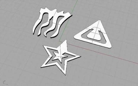
Figure 8: Three examples of “paperclips” created during W.I.S.E. as seen in Rhinoceros.
The participants are then excused for lunch. Files are checked, exported to Catalyst, and sent to the RP machine. When the participants arrive later that afternoon they are able to hold the “paperclips” in their hands. Each group then presents their design from sketch to tangible prototype. They test the function of each clip and evaluate their success. Participants comment freely on the aesthetic choices and function of one another’s designs. This critique experience allows the participants to get a good look at other solutions to the design problem as well as have some practice in verbalizing their own motivations and realizations.
While all of the paperclips created are not groundbreaking or even functional, the session provides other viable results. After establishing a common idea of what design is early on, the participants leave with an appreciation of the ways in which things are created both commercially and artistically. Participants are given experience with industry standard technology and computer aided design software. They are challenged to problem solve, evaluate, and report their findings. Later, individuals stated in the program evaluation that they were really excited to see their finished products and that they found designing the paperclip the most interesting event of the day because they were able to make something that has never been made before.
This outreach is just one of the many ways the technology is successfully working to the advancement of Penn State Altoona, its faculty, and students.
FUTURE DIRECTIONS
The EMET program at Penn State Altoona is evolving toward a straight four-year degree rather than a 2+2 program, and part of the evolution includes incorporating more design experiences earlier in the curriculum. Courses are being examined for inclusion of design components, and ideas being generated for new courses that would bolster the capstone design course as well as design skills in general. The FDM is being considered for permanent inclusion in mechanical technology courses, including a course in dynamics and machine elements and a course in machine element design. The anisotropic strength of the material along with its other properties, in comparison with metal alloys, will provide valuable experience in material limitations and selection. A strong CAD emphasis in the program, including Pro/Engineer and AutoCAD, could be greatly enhanced by routinely including actual part fabrication as part of the experience.
The continued collaboration between art and engineering is at the heart of the most interesting aspects of future possibilities. Team-taught (art and engineering faculty) design courses, joint research projects, guest lectures and expansion of outreach efforts with participation from both areas are just a few of the opportunities opened up by the nascent collaboration. Other campus department collaborations may also open up: recent collaborations outside engineering include the tangible visualization of biofilms for a Penn State Altoona biology faculty member’s research.
As the technology increasingly becomes more affordable and evolves to include more materials like ceramic, glass, and metal the output from rapid prototyping can only become more significant at Penn State Altoona. Currently, the chess sets created within ART 100 are on permanent display in the Chancellor’s office.
CONCLUSION
The introduction of a FDM at Penn State Altoona was a watershed event in the engineering and art programs. For engineering, although parts produced by the device have limited application as structural elements, the speed and accuracy of the fabrication, the user-friendly design environment, the ability of the machine to produce complex parts and the lightweight material are major advantages, especially in the context of the senior capstone project.
The FDM has also been used successfully to support the broader mission of the campus, especially recruitment, through the middle school program. The greatest value of the FDM, though, may well be the collaboration between art and engineering. As both programs evolve, joint efforts, begun with the FDM, will be one of the keys to success in both areas.
REFERENCES
[[1]] World-Wide Web URL http://cede.psu.edu/StudentGuide. Last Accessed December 16, 2004.
[[2]] World-Wide Web URL http://www.rhino3d.com. Last Accessed December 16, 2004.
[[3]] Liou, Frank, Venkat Allada, Ming Leu, Rajiv Mishra and Anthony Okafor. An Integrated and Distributed Environment for a Manufacturing Capstone Course. 2003 ASEE Annual Conference and Exposition, June 22-25, 2003, Nashville, Tennessee.
[[4]] Hoekstra, Nicole. Tool Design and Concurrent Engineering Using Rapid Tooling Construction Methods. 2000 ASEE Conference and Exposition, St. Louis, Missouri, June 18-21, 2000.
[[5]] McGeen, Michael J. Architectural Engineering Applications of Rapid Prototyping. 2002 ASEE Annual Conference & Exposition, Montréal, Quebec, Canada, June 16-19, 2002.
[[6]] Zecher, Jack. Integration of a Rapid Prototyping System in a ME T Curriculum. 1998 ASEE Annual Conference & Exposition, Seattle, Washington, June 28-July 1, 1998.
[[7]] Wells, Robert Lindsay, Donald L. Goddard and Jeffrey R. Mountain. Integrating the Product Realization Process into a Mechanical Engineering Curriculum using Desktop Manufacturing Equipment. 2001 ASEE Annual Conference and Exposition, Albuquerque, New Mexico, June 24-27, 2001.
[[8]] Coulter, John P., Herman F. Nied, Charles R. Smith and David C. Angstadt. Involving Middle School Students in Customer Focused Undergraduate Manufacturing Education. 2003 ASEE Annual Conference and Exposition, June 22-25, 2003, Nashville, Tennessee.
[[9]] Umashankar, R., T.A. Anderson, C.Y. Choi, A. Ortega, R. Vaidyanathan, G. Artz, M. Platero and R. Sharma. Summer Engineering Academy (SEA), An Innovative University-Industry Partnership to Improve the Recruitment of Qualified High-School Students Into Engineering Disciplines. 2001 ASEE Annual Conference and Exposition, Albuquerque, New Mexico, June 24-27, 2001.
[[10]] Musto, Joseph C., W. Ed Howard and Stephen Rather. The RP Derby: A Design/Build/Test Experience for High School Students. 2000 ASEE Conference and Exposition, St. Louis, Missouri, June 18-21, 2000.
[[11]] World-Wide Web URL http://www.stratasys.com. Last accessed December 16, 2004.
[[12]] Ahn, Sung-Hoon, Michael Montero, Dan Odell, Shad Roundy and Paul K. Wright. Anisotropic Material Properties of Fused Deposition Modeled ABS. Rapid Prototyping, Vol. 8, No. 4, 2002, pp. 248-257.
[[13]] Noorani, Rafiq, Omar E-Said, Joe Foyos, Anthony Barrata and Boris Fritz. Impact of New Technologies on Integrated Product Development. 1999 ASEE Annual Conference and Exposition, Charlotte, North Carolina, June 20-23, 1999.
[[14]] Avallone, Eugene A. and Theodore Baumeister III. Marks’ Standard Handbook for Mechanical Engineers, Tenth Edition. McGraw-Hill, 1996, p. 6-54.
[[15]] World-WideWeb URL http://www.buildfdm.com/data/product_brief_matspecs.pdf. Last Accessed December 16, 2004.
[[16]] Avallone, Eugene A. and Theodore Baumeister III. Marks’ Standard Handbook for Mechanical Engineers, Tenth Edition. McGraw-Hill, 1996, p. 6-186.
[[17]] Vavreck, Andrew N. Project Management Applied to Student Design Projects. 2002 ASEE Annual Conference & Exposition, Montréal, Quebec, Canada, June 16-19, 2002.
BIOGRAPHIES
REBECCA A. STRZELEC is Assistant Professor of Visual Arts at Penn State Altoona. She joined the faculty at Altoona College in August 2002, after completing her BFA and MFA in Metals/Jewelry/CAD-CAM at Tyler School of Art, Temple University. She teaches a variety of courses for the School of Visual Arts and the Integrative Arts program at Altoona. Her work is exhibited widely nationally and internationally.
ANDREW N. VAVRECK is Associate Professor of Engineering and Head, Division of Business and Engineering at Penn State Altoona. He earned his B.S. (Engineering Science, 1982), M.S. (Engineering Mechanics, 1988) and Ph.D. (Engineering Science and Mechanics, 1997) degrees from Penn State University. Dr. Vavreck teaches a variety of courses to undergraduate engineering and engineering technology students. His research is in adaptive-passive materials design and application.