
Volume 2, Number 2, Spring 2002
Using Pulse Amplitude Modulation
to Instruct
Engineering
Technology Students
In
Digital Communications
Willie Ofosu
Pennsylvania State University: Wilkes-Barre
Lehman, PA 18627-0217
E-mail: wko1@psu.edu
Abstract
Digital communication is central to successful information technology operations in both the work place and at home. One of the techniques employed in digital communications is pulse amplitude modulation (PAM). This makes PAM an essential part of the curricula for telecommunications engineering technology students. PAM is an amplitude modulated (AM) form of pulse carrier [1], and hence has all the advantages and disadvantages of purely analog AM, a major disadvantage being noise. It is used extensively in telecommunications as an intermediate step of other techniques such as quadrature amplitude modulation (QAM), and pulse code modulation (PCM) [2] which is used in the public switched telephone network (PSTN). One useful approach to instructing technology students is by starting with a topic that is central to many applications. PAM is one such topic. This paper discusses the advantages of using a laboratory experiment to introduce engineering technology students to the PAM technique as an initial stage in instructing them in digital communications.
Introduction
Hands-on experiential instructional processes characterize engineering technology programs. This method of instruction is particularly useful for graduates who seek employment in industries that are service and maintenance oriented. The hands-on experiential approach may not be sufficient in cases where the graduate intends to seek employment in a research establishment. It is generally believed that students preparing for employment in research establishments require a higher level of mathematical utilization than students in technology programs do. It is, however, essential that technology students understand all the principles employed in any particular technology that is taught in their program.
The Telecommunications industry has both research, and service and maintenance companies. Service and maintenance oriented companies outnumber research establishments, and the majority of graduates find jobs in the profit driven service and maintenance sector. Here, the more work that is completed, the higher the profits. This creates an environment where service is generally not taken to the component level where design may be needed, but to the card level where faulty cards are simply replaced. It is therefore essential for the students to know how a card in working order should perform and how to obtain correct signals from test points on the card. It is important, however, that the student has some knowledge at the component level with respect to bipolar junction transistors (BJTs) and integrated circuit (IC) chips. The student should also know how to technically interpret the signals to make a correct diagnosis. This paper discusses a laboratory experiment for telecommunications engineering technology students to supplement a lecture on how to extract useful information from a PAM signal. This exercise is used in an intermediate telecommunications technology class.
Telecommunications Technology Program
The 2-year Associate Degree program in Telecommunications Engineering Technology at Penn State Wilkes-Barre was initially mainly analog, and was designed to supply the telephone industry with technologists. The growth in the telecommunications industry has necessitated upgrading the program to meet current industrial practices. The new program is mostly digital to reflect the current industrial practices. The program is designed to combine hands-on and traditional learning styles to produce technologists who are able to solve problems using theoretical and practical skills through critical thinking. Currently the program consists of topics in Data, Voice and Video transmissions for both Wireline and Wireless applications. The current industrial focus on the Internet is also catered for in courses on Networking and Protocols. As telecommunications has become a global practice, students of the program at Wilkes-Barre are exposed to national as well as international standards.
Pulse Modulation Techniques in Digital Communications
Pulse modulation techniques are extensively used in digital communications, and an AM form of pulse carrier is one of the simplest among the different techniques. Technology students find AM easy to understand because the mathematics involved is minimal. Topics such as sampling and quantization need to be addressed, but these are not difficult mathematical concepts to teach. The fact that PAM can be time-division multiplexed and is used as a starting technology for PCM helps students to appreciate the involvement of PAM in the PSTN. PSTN is a practical application that the students are very familiar with. Technology students are usually focused on applications, and at this stage, other applications based on PAM are discussed. Examples include the use of PAM to produce high-level modulation schemes for data modems and digital radio. Students use modems regularly, and are familiar with digital radios. This introduction helps to focus the students’ attention and facilitates discussion of pulse modulation techniques used in digital communications. These are the advantages in using the PAM technique.
Other common types of pulse modulation [1] techniques discussed in class are pulse width modulation (PWM), sometimes called pulse duration modulation (PDM) or pulse length modulation (PLM), pulse position modulation (PPM), and pulse code modulation (PCM). PWM and PPM are used in few instances in communications systems. PWM is used in high-powered audio amplifiers that are used to modulate amplitude modulated (AM) transmitters [3]. It is also used in telemetry systems. PWM is not sensitive to amplitude changes as a result of noise and distortion. PPM is also applied in telemetry systems. These two are rarely used in commercial multiplexed communications systems [2] because of the large bandwidths needed. Also, the fact that frequency division multiplexing (FDM) must be used with these two makes them unsuitable for commercial communications systems because the equipment needed for FDM is more complex hence more expensive than that needed for TDM. Again, with PPM, a phase-locked loop needs to be used so as to employ its acquisition circuitry. PCM is dealt with in its application in long-distance communications. To complete this instructional process, hands-on laboratory activities are conducted to give the students practical knowledge to complement the lectures.
A laboratory exercise on PAM signal is used to start the laboratory component of the course. It also gives the students a visual experience on the effects of the technique. The exercise shows how a PAM generator creates a PAM signal from a sine wave, and how the PAM signal is demodulated to reconstruct the original signal.
Experimental Exercise
The experiment is performed with Lab Volt Digital Communications Trainer Model
8085. Lab Volt provides equipment designed for laboratory exercises in universities and colleges. Other providers of such equipmentare Emona Instruments and Feedback Ltd. The experimental circuits of the trainer are designed on cards as modules that can be connected to the power supply and measuring components to form specified modular arrangements. Experimental procedures are provided with the trainer. These can be modified to suit particular preferences. The experimental set up used for the PAM experiment is shown in Figure 1.
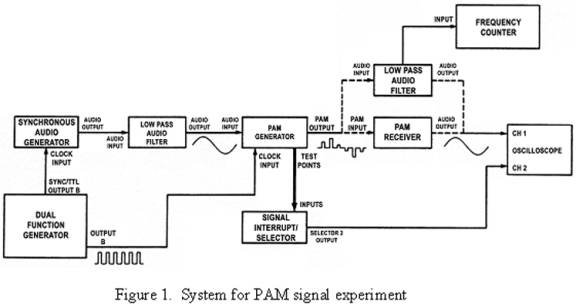
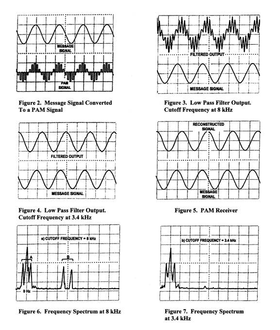
A PAM generator is used to construct a PAM signal form of a sine wave output from an audio generator. This is shown in Figure 2. The PAM signal is demodulated by two methods. One method uses a low pass audio filter, and the other method use a PAM receiver fixed at 3.4 kHz to allow good reception of the International Telecommunications Union (ITU) standard bandwidth signal. The PAM receiver has a high-order low pass filter incorporated. Measurements are taken at 8 kHz, and at 3.4 kHz in both time and frequency domains.
With the PAM generator set to message signal, the output is connected to the low pass filter with the cutoff frequency set at 8 kHz. The output and the message signals are shown in Figure 3. The noise observed in the output is greatly reduced when the cutoff
frequency of the low pass filter is reduced to 3.4 kHz. This is shown in Figure 4. Figure 5 shows the output of the PAM receiver when the signal from the PAM generator is subsequently connected to the PAM receiver. A spectrum analyzer is then connected between the low pass filter and the oscilloscope. The output is first observed from the low pass filter at 8 kHz, then at 3.4 kHz. The responses are shown in Figures 6 and 7 respectively. This step is repeated with the PAM receiver. The spectrum observed from the output of the PAM receiver is similar to Figure 7.
Discussion of Laboratory Exercises
This laboratory exercise exposes students to various concepts applied in the transmission and reception of information. When the cutoff frequency of the low pass filter is set at 8 kHz, the bandwidth for the signal is set at that frequency and the response is very noisy (Figure 3). In real life situations, the noise can be from both external and internal (unwanted frequencies such as replicas generated by the system) sources. This helps students to understand the effects of harmonic distortion when replicas of the fundamental signal are not completely filtered out. When the cutoff frequency is reduced
to the ITU recommended standard of 3.4 kHz, the noise is significantly reduced as the filter smoothes out the reconstructed PAM signal, although the output is still not as smooth as the message signal (Figure 4). Reducing the cutoff frequency to 3.4 kHz demonstrates selectivity to the students. The output from the PAM receiver is an exact replica of the message signal (Figure 5), and further demonstrates selectivity. Also, the PAM receiver is more sophisticated in construction than a simple low pass filter.
In all these figures, the output signal is out of phase with respect to the input signal. This is due to delay of the signal as it passes through the system. The effect of the delay will not be noticeable to the operator. During the experiment, the sampling rate is varied around the minimum Nyquist rate of 2fmax where fmax is the highest frequency of the input signal. When students vary the sampling rate, they observe aliasing or foldover distortion, and understand the need for using the minimum Nyquist rate or a little above that value. When students vary the duty cycle, they observe aperture distortion. Compensating networks have to be used for a duty cycle of more than 10 %. Figure 6 is the frequency spectrum of the output response at 8 kHz showing the message signal plus a harmonic or
a replica at a higher frequency. The frequency domain representation helps the students to understand the time domain effect in Figure 3 where the replica manifests as noise on the channel. When the cutoff frequency is reduced to the recommended standard of 3.4 kHz, Figure 7, the unwanted frequencies are removed.
Applications of Subject Matter
The PAM exercises described above forms part of the course content of Telecommunications 243 (Telcm 243) and Telecommunications 244 (Telcm 244). These courses are part of the 2-year Associate Degree program in Telecommunications Engineering Technology. Because students on this program also take courses that make them eligible for the Associate Degree in Electrical Engineering Technology (EET), they are eligible to transfer into the 4-year Bachelor of Science EET (BSEET) program. At the Junior and Senior levels of the 4-year BSEET program, students go on to take Electronic Engineering Technology 478 (EET 478), which is Digital Communications where multi-level digital modulation topics such as QAM are discussed. Observations of students in EET 478 who have taken Telcm 243 and Telcm 244 show that they are more involved in class discussions and respond more readily to questions that relate to the PAM technique. During laboratory sessions, students perform more competently on their own in exercises based on the PAM technique.
Conclusion
Pulse amplitude modulation (PAM) has proved to be a very effective first step in introducing digital communications to telecommunications engineering technology students. Understanding of PAM forms a good foundation for the study of other techniques that use PAM as an intermediate step. Students who have had a learning experience with PAM seem better able to assimilate instruction in other pulse modulation techniques, as well as in digital technologies that employ PAM.
The hands-on approach used in the experimental procedure helps students to become familiar with the output waveforms expected from a properly functioning circuit and to understand changes that can occur to the expected waveforms when faulty conditions are simulated. Telecommunications concepts such as aliasing, aperture distortion, bandwidth, and Nyquist sampling rate for a particular transmission are well demonstrated by the experiment. This reinforces the learning process started with a lecture.
The usefulness of PAM is emphasized by the research still going on, such as on error probabilities for QAM systems [4], and communication systems with cascaded sequences and PAM/QAM signal sets [5].
References
[1] Electronic Communication Techniques, 4th Edition, Paul H. Young, Prentice Hall,
1999, Chapter 11.
[2] Electronic Communications Systems, Fundamentals Through Advanced, 4th Edition, Wayne Tomasi, Prentice Hall, 2001, Chapters 3 and 15.
[3] Comprehensive Electronic Communication, Roy Blake, West Publishing Company, 1997, Chapter 11.
[4] Error probabilities for QAM systems on partially coherent channels with intersymbol interference and crosstalk, Carlos Rivera et al., IEEE Transactions on Communications, vol. 46, No. 6, June 1998
[5] TCM/SSMA communication systems with cascaded sequences and PAM/QAM signal sets, Tsao-Tsen Chen et al., IEEE Transactions on Communications, vol 46, No. 7, July 1998
Willie K. Ofosu
Willie K. Ofosu is an Assistant Professor and Head of Telecommunications Engineering Technology program at Penn State Wilkes-Barre, where he teaches telecommunications and electronic engineering. His research interests are in RF components and antennas. Technology. He is an advocate of diversity in the educational environment. His work involves partnerships with some industries in the Telecommunications field. Dr. Ofosu received his Ph.D. from the Electronic Systems Engineering Department at University of Essex (England) in 1994.