
Wajiha Shireen IEEE Senior Member
University of Houston
Rahul A. Kulkarni
IEEE Student Member
University of Houston.
ABSTRACT
In this paper analysis of a three phase PWM inverter system, with harmonic assessment of the inverter input current and output voltage with balanced and unbalanced loads, is presented. The analytical procedure and the simulation results presented show how MATLAB can be used as an effective tool to analyze a PWM inverter. Advantages of using MATLAB are the following: faster response, availability of various simulation tools and functional blocks and the absence of convergence problems. The analytical procedure and simulation outlined in this paper can be used as an educational tool to make the concepts of modern power conversion schemes comprehensible to students. The proposed switching function approach can be an effective research tool to model different power conversion circuits in MATLAB.
INTRODUCTION
Pulse Width Modulated (PWM) inverter systems are used in a wide variety of applications as a front-end power-conditioning unit.
Applications of PWM inverter systems:
· Electric drives
· Uninterruptible power supplies
· High voltage DC transmission
· Active power filters and reactive power compensators in power systems
· Electric vehicles
· Alternate energy systems
· Industrial processes
Inverters realize dc-to-ac power conversion and in the most commonly used voltage source inverter configuration, the dc-input voltage can be obtained from a diode rectifier or from another dc source such as a battery. A typical voltage source PWM inverter system consists of rectifier, DC-link, PWM inverter along with associated control circuitry and the load. Most modern voltage-source inverters are controlled using a wide variety of pulse width modulation (PWM) schemes, to obtain output ac voltages of the desired magnitude and frequency shaped as closely as possible to a sine wave.
Analysis of PWM inverter systems is required to determine the input-output characteristics for an application specific design, which is used in the development and implementation of the appropriate control algorithm. In addition to time domain analysis, harmonic assessment is an integral part of analysis and simulation of any power conversion system. Several powerful computer simulation tools, such as PSPICE, SABER and MATLAB, are available that can be effectively used to analyze and design PWM inverter systems. Advantages of using MATLAB are the following: faster response, availability of various simulation tools and functional blocks that makes the simulation process simpler. And MATLAB does not suffer from convergence problems as in the case of other software tools.
Analysis and design of PWM inverter systems have been mainly based on supplying balanced and linear loads [1]. However, the general drive towards automation has increased the use of a spectrum of new loads, such as computers with peripherals, telecommunication equipment, industrial robots etc. A large majority of these new loads are unbalanced and/or nonlinear in nature. In view of this, this paper presents the analysis of a three-phase PWM inverter system including harmonic assessment of the inverter input current and output voltage with balanced and unbalanced loads. Analytical equation using the switching function approach is used to find the proper state equations to describe the power conversion circuit in MATLAB [2]. Recent research has shown that the switching function concept is a powerful tool in analysis static power converters [3]. Switching functions are Fourier Series representation of the switching sequence used for PWM control of the inverter switching devices. In the paper, the switching function approach used to derive the state equations is described, and simulation results from the MATLAB program are presented. Effects of balanced and unbalanced loads on the harmonic contents of the inverter-input current are presented. The analytical procedure and simulation outlined in this paper can be used as an educational tool to make the concepts of modern power conversion schemes comprehensible to students. The harmonic assessment of input-output parameters presented in the paper is especially important to introduce the students to the harmonic related power quality issue faced by modern power systems, when loaded with different application specific power conversion equipment.
ANALYSIS OF A THREE PHASE PWM INVERTER
Figure 1 shows a typical three phase PWM inverter system. The dc-input for the three phase inverter is obtained by rectifying a 60 Hz ac source by means of a diode rectifier. The DC-link components L and C are so selected that the voltage Vdc at the inverter input is constant and ripple free. The semiconductor switching devices in the inverter are controlled by PWM signals generated by a control circuit in order to obtain three phases? near sinusoidal ac voltages of the desired magnitude and frequency at the inverter output.
In order to analyze the PWM inverter system in MATLAB, it is important to compute a dependent variable (input current, output voltage) in terms of an independent variable (input voltage and output current). The transfer function approach is used to describe the inverter operation.
For a three phase inverter, the transfer function (T) is composed of three independent switching functions and is given by,
T = [S1 S2 S3] (1)
The switching functions are Fourier Series representation of the switching sequence used for PWM control of the inverter switching devices. Mathematical representation of switching functions are given by,
![]() +
+
![]() (2a)
(2a)
![]() (2b)
(2b)
![]() (2c)
(2c)
Where A0 represents the dc value and w is the desired frequency at the inverter output. The switching functions were generated by using the Sinusoidal Pulse Width Modulation (SPWM) technique, as shown in Figure 2. The “saw tooth” function in MATLAB was used to generate the carrier signal of the desired frequency. The carrier signal frequency used for the simulation was 1980 Hz. The switching function S1 for phase ‘a’ of the inverter was generated by comparing the carrier signal with modulating signal Mod_a. Similarly, switching functions S2 and S3 can be obtained by comparing carrier signal with modulating signals Mod_b and Mod_c for phases ‘b’ and ‘c,’ respectively. Figure 3 shows the switching function S1, and Fig. 4 shows its frequency spectrum. The frequency spectrum of any periodic signal can be obtained by using the FFT function in MATLAB. It can be seen from Fig. 4 that the switching function consists of the fundamental 60 Hz component and higher order harmonics. Lower order harmonics up to the 33rd (1980 Hz) have been eliminated by the SPWM strategy.
Based on the switching functions (transfer function, T), the dependent variables of the inverter system, such as the input current and output voltages, can be calculated from the independent variables.
INVERTER WITH BALANCED LOADS
Assuming star connected balanced loads at the output of the inverter with impedance Z, the inverter line to neutral output voltage (V) is given by,
![]() (3)
(3)
Where Vdc is the inverter input voltage. The line to neutral voltage Van is a pulse width modulated waveform similar to the switching function S1. The pulse magnitudes in Van vary from 0 to Vdc/2 whereas S1 varies between 0 and 1.
The inverter output line currents can be computed as,
![]() =
=
![]() (4a)
(4a)
![]() (4b)
(4b)
![]() (4c)
(4c)
Where, j is the impedance angle.
The three phase output currents of the inverter can be represented by,
![]() (5)
(5)
Hence, the inverter input current Ii can be computed as,
![]() (6)
(6)
From equations (1) and (2) the input current can be written as,
![]() (7)
(7)
The mathematical operation in equation (7) was performed in MATLAB to obtain the inverter input current for balanced loads and its corresponding frequency spectrum as shown in Figures 5 and 6, respectively. From Fig. 6 it can be seen that the inverter input current with balanced loads consists of a dc component and higher order switching frequency harmonics (1980 Hz and above). The inverter line-to-line output voltage can be generated using the line to neutral voltages.
![]() (8)
(8)
Figure. 7 shows the inverter line to line output voltage, and Fig. 8 shows its frequency spectrum. It can be seen that the line-to-line voltage varies between 1, 0 and –1. The output voltage consists of the fundamental (60 Hz) component and higher order switching frequency harmonics as can be seen from the FFT shown in Fig. 8. By increasing the frequency of the carrier signal in the PWM strategy, the higher order harmonics can be pushed further along the frequency axis, making the inverter output voltage more closely resemble a pure sine wave.
INVERTER WITH UNBALANCED LOADS
If three phase unbalanced loads Za, Zb and Zc are connected at the inverter output, the three phase unbalanced currents can be calculated as,
![]() (9a)
(9a)
![]() (9b)
(9b)
![]() (9c)
(9c)
Where, I1, I2, I3 represent the current magnitudes and q1, q2, q3 are the impedance angles. The same approach used for balanced loads can be used to plot the inverter input current. Figure 9 illustrates the inverter input current with unbalanced loads, and its frequency spectrum is shown in Figure 10. It can be seen from Fig. 10 that in addition to the dc component, the inverter input current consists of a 60 Hz and a 120 Hz component. These lower order harmonics are not present in the inverter input current spectrum for balanced loads (Fig. 6). Hence, unbalanced loads generate abnormal harmonics at the inverter input.
CONCLUSIONS
The analytical procedure and simulation results presented in this paper show how MATLAB can be used as an effective tool to analyze PWM inverter systems. Simulation results for both balanced and unbalanced loads were presented. A similar approach can be used to analyze/predict the inverter dependent variables with nonlinear loads. The appearance of abnormal harmonics at the inverter input, due to load unbalance at the inverter output, may pose a problem in some applications. This opens possibilities of new research directions involving the reduction or elimination of these abnormal harmonics.
References
[1] L. Salazar and G. Joos, “ PSpice Simulation of Three Phase Inverter by means of Switching Function”, IEEE Trans. on Power Electronics, Vol. 9, No. 1, Jan. 1994.
[2] P. Enjeti and P. D . Ziogas, “ Analysis of a Static power converter under unbalance”, IEEE Transactions in Industrial Electronics, Vol. 37, No. 1, February 1990.
[3] Lee B. -K, Ehsani M, “A simplified functional simulation model for three-phase voltage-source inverter using switching function concept”, IEEE trans. on Ind. Electronics, v 48,n 2, April 2001, p309-321.
Figure 1: A typical three phase PWM inverter system
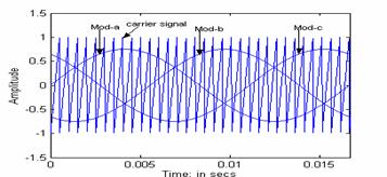
Figure 2: Sinusoidal pulse width modulation
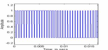
Figure 3:Switching Function S1 for phase ‘a’
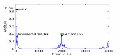
Figure 4: Frequency Spectrum of Switching Function S1
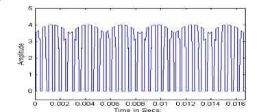
Figure 5: Inverter Input Current for Balanced Loads
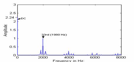
Figure 6: Frequency Spectrum of Inverter Input Current for Balanced Loads
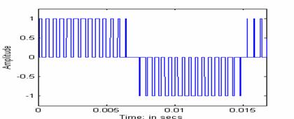
Figure 7: Inverter line-to-line output voltage
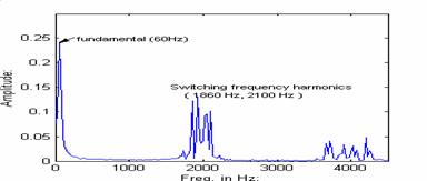
Figure 8: Frequency spectrum of line-to-line output voltage
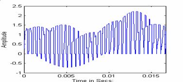
Figure 9: Inverter Input Current for unbalanced loads
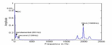
Figure 10: Frequency Spectrum Of Inverter Input Current for Unbalanced Loads